Below is the code that can be used in Arduino Sketch to assign the Wemos D1 R32 IO pins for Arduino compatibility
#ifdef ESP32
#define A0 2
#define A1 4
#define A2 35
#define A3 34
#define A4 36
#define A5 39
#define A6 32
#define A7 33

#define D2 26
#define D3 25
#define D4 7
#define D5 16
#define D6 17
#define D7 14
#define D8 12
#define D9 13
#define D10 5
#define D11 23
#define D12 19
#define D13 18
#endif
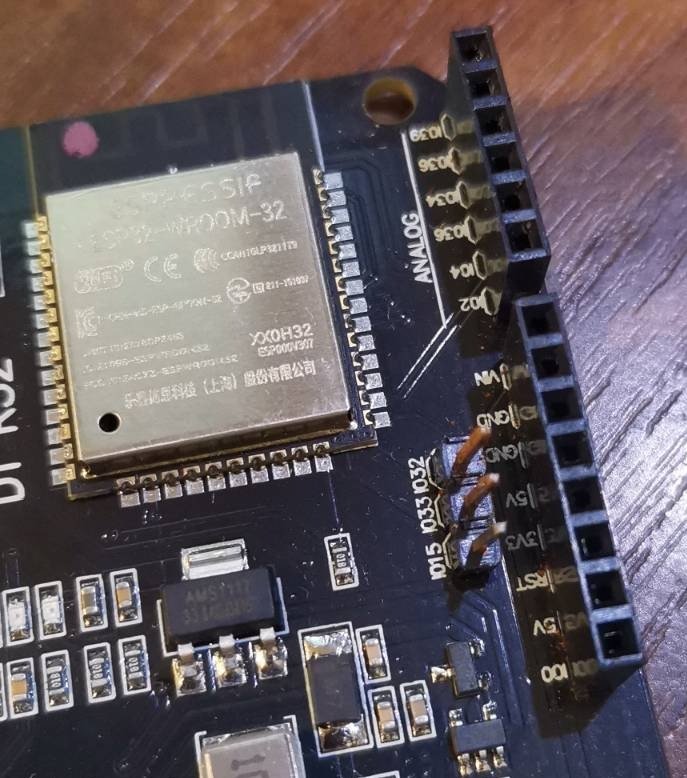
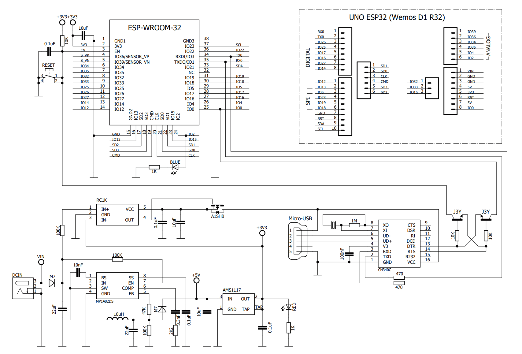
Analog inputs A6 and A7 do not have a pin present, but they can be attached later, they are accessible on the board like IO32 and IO33.
Note:
- A0 and A1 are not reliable, no matter how the software or hardware is configured, the returned value is not correct, grounding does not reduce the input to zero, use A6 and A7 instead!
A0 & A1 is GPIO2 & GPIO4 in UNO ESP32 and these can sense variations in anything that holds an electrical charge, because at the hardware level they are internal capacitive touch sensors! - Using
pinMode(AnalogPin, INPUT_PULLUP)has no effect, the voltage read on the pins is not 4095 (as it should be) but random.
Input only pins: GPIOs 34 to 39 are GPIs . These pins don’t have internal pull-up or pull-down resistors. They can’t be used as outputs, so use these pins only as inputs:
In conclusion, the GPIO analog pins must be connected physically correctly, it is mandatory that they do not remain floating, without connection. Even unused analog pins must be connected to ground or through a 10k resistor at 3.3V!
At the hardware level, A0 (IO2 in UNO ESP32) is already connected to ground through a blue LED
Important:
Do not use 5V on the input pins of the board or sensors, unless you use a voltage divider at the input or use only 3.3V!
Be First to Comment